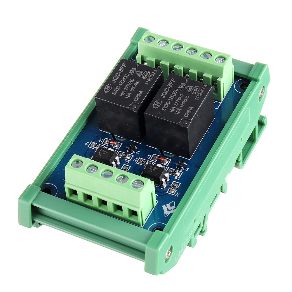
5pcs 2CH Channel Optocoupler Isolation Relay Module 5V SCM PLC Signal Amplifier Board

5pcs 2CH Channel Optocoupler Isolation Relay Module 5V SCM PLC Signal Amplifier Board
5pcs 2CH Channel Optocoupler Isolation Relay Module 5V SCM PLC Signal Amplifier Board5pcs 2CH Channel Optocoupler Isolation Relay Module 5V SCM PLC Signal Amplifier Board5pcs 2CH Channel Optocoupler Isolation Relay Module 5V SCM PLC Signal Amplifier Board


Structural Features:


1. Use Hongfa relay, stable and reliable performance;

2. Compatible with two input modes of positive control and negative control;

3. Each channel has an LED action indicator for a more intuitive understanding of product performance;

4. Each channel adopts optocoupler isolation to enhance anti-interference performance and isolation performance;

5. At the same time, the power supply and the "IN" control terminal are independently controlled;

6. The module adopts the standard "DIN" rail-type installation design, which is convenient and quick to install, firm and stable.


Technical Parameters:


1. Trigger signal: DC5V

2. Each trigger signal current: 5mA

3. Power supply voltage: DC5V

4. Each coil current: 18.8mA

5. Contact type: one normally open and one normally closed (single pole)

6. Maximum load current of each contact: 10A

7. Action time: below 12ms

8. Reset time: less than 4ms

9. Maximum switching frequency: 18000 times / hour

10. Mechanical life: more than 20 million times

11. Relay installation: plug-in type (No)

12: Module installation method: DIN standard rail installation

Positive control wiring introduction:


1. Power input terminal:

VCC is connected to the positive voltage, GND is connected to the negative voltage, and S / S is connected to the negative voltage

IN1, IN2 are connected to positive voltage control, IN1 controls  terminal, IN2 controls K2 terminal

2. Control device output:

The output terminal is clearly marked with 234, 3 is a common point, 2 is normally open, and 4 is normally closed. K1, K2 means two relays work.


Negative control wiring introduction:


1. Power input terminal:

VCC is connected to the positive voltage, GND is connected to the negative voltage, and S / S is connected to the positive voltage

IN1, IN2 are connected to negative voltage control, IN1 controls  terminal, IN2 controls K2 terminal

2. Control device output:

The output terminal is clearly marked with 234, 3 is a common point, 2 is normally open, and 4 is normally closed. , K2 means two relays work.

Package includes:

5 x Relay board


5pcs 2CH Channel Optocoupler Isolation Relay Module 5V SCM PLC Signal Amplifier BoardSee detail


Popular posts from this blog

DIY Qi Standard Wireless Charging Coil Receiver Module Circuit Board DIY Coil for Phone for Battery 5V 1A Fast Quick Charger

Get DIY Qi Standard Wireless Charging Coil Receiver Module Circuit Board DIY Coil for Phone for Battery 5V 1A Fast Quick Charger Features:   1. Pure copper coil, high permeabillity, low loss, assuring fast charging. 2. Can charge the battery directly. 3. Charging current is around 5V 1A. 4. Can be directly connected to the phone's motherboard, the phone will display wireless charging. 5. Red is positive and gold is negative. The wire can be bent freely.   Specification:   Material: PCB Product Name: Wireless Charger Receiver Module Input Power: 5V 1A or 9V 0.5A Output: Power up to 5W Charging Efficiency: 75% Transmission distance: 2-8mm Charger Applicable Form: Wireless Charger Executive Standard: Qi Wireless Charging Standard Product Certification: CE/FCC/ROSH Board Size: 1.9 * 3.2cm / 0.7 * 1.3in Copper Coil Size: 4.1 * 2.9cm / 1.6 * 1.4in Cable Length: 5cm / 2.0in Weight: approx. 6g   Note:   Wireless charging = transmitter + receiver (both can be charged together) 1, there...

433MHz 12V 4CH Channel Relay RF Wireless Remote Control Switch 2 Transmitter+Receiver

Get 433MHz 12V 4CH Channel Relay RF Wireless Remote Control Switch 2 Transmitter+Receiver Feature:   Remote Control Distance: 100 meter(open/ideal) in theory, 10%-50% in reality(In open environment) Encode: Fixed code, soldering Frequency: 433mHZ Channel: 4 CH Power Supply: DC 12V Relay: DC 12V Quiescent Current: 8mA Work Voltage Range of Relay: AC 110-240V or DC 0-28V Sensitivity:-105 dBm Operating Temperature: -40℃~80℃ Receiver Size: 68x47x17mm   Control Mode:   1. Toggle/Self-Lock: Press->On; Press again->Off press one button for one time is working/ON .press the same button again is stop/OFF . (1 channel switch(receiver) need 1 button remote control (transmitter). 2. Latched/Inter-Lock: Press->On; Press other button->Off press one button is working/ON ,press another button is stop/OFF . ( 1 channel switch( receiver) need 2 buttons remote control (transmitter). 3. Momentary/Jog: Press and hold->On; Release->Off Keep pressing one button is working /ON. loosen you...

10pcs Thermal Sensor Module Temperature Switch Thermistor Sensor Board For Arduino

Get 10pcs Thermal Sensor Module Temperature Switch Thermistor Sensor Board For Arduino Uses:   Temperature detection, temperature control sensors , ambient temperature detection   Features:   1. Using the NTC thermistor sensor, good sensitivity 2. The comparator output signal is clean, good waveform, driving ability, more than 15mA. 3. Adjust the temperature distribution position detection threshold 4. The working voltage 3.3V-5V 5. The output format: digital switching outputs ( 0 and 1 ) 6. Fixed bolt holes for easy installation 7. Small PCB board size: 3.2cm x 1.4cm 8. Using a wide voltage LM393 comparator   Module for use:   1. The thermal resistance of the module is very sensitive to the ambient temperature, typically for detecting the temperature of the surrounding environment ; 2. Through the potentiometer adjustment, you can change the temperature detection threshold ( ie, control temperature ), such as the need to control the ambient temperature is 50 degrees, the module i...